Instrument Air Packages: Actuator Air Systems and More

October 28, 2024

Actuator air systems play a crucial role in modern industrial applications. These systems utilize compressed air to power pneumatic actuators, enabling precise control and movement in various machinery and equipment. From single acting pneumatic actuators to complex valve actuation systems, the use of air pressure has revolutionized automation across industries.


This article explores the world of actuator air systems and their components. It delves into different types of actuators used in industrial settings, examines control systems and speed controllers, and introduces the eco piston – a zero emissions actuator. By understanding these key aspects, readers will gain insight into the operation and importance of pneumatic actuation systems in today’s manufacturing and process control environments.

Types of Actuators Used in Industrial Applications

These devices are commonly found in manufacturing, packaging, food and beverage, and automation industries. Pneumatic actuators offer high force and speed in a compact design, making them suitable for applications requiring rapid movement and flexibility.


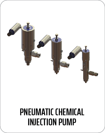
Pneumatic actuators come in different configurations, including single-acting and double-acting types. Single-acting pneumatic actuators use air pressure to move in one direction and a spring return to return the original position. Double-acting actuators, on the other hand, employ air pressure for movement in both directions. These actuators can provide both rotational and linear motion, allowing for versatility in automated processes.

Air Actuators vs. Electric Actuators

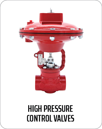
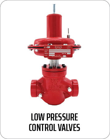
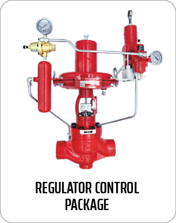
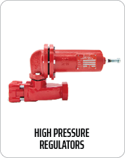
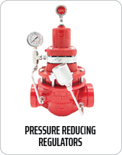
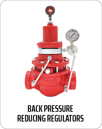
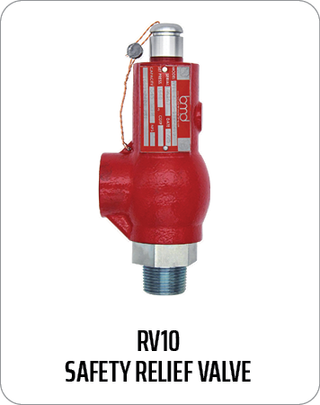
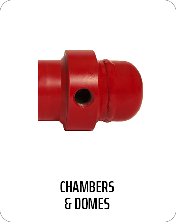
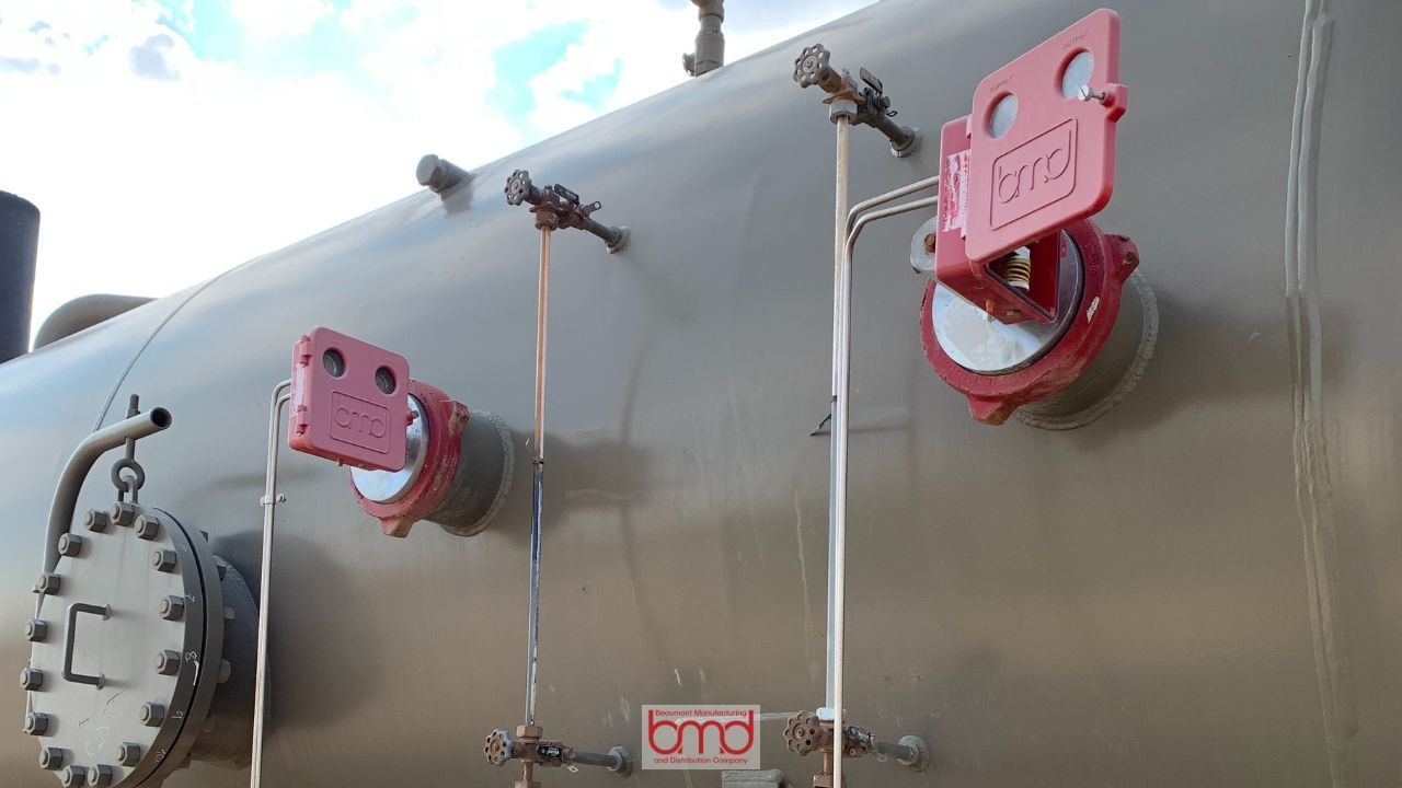
When comparing pneumatic and electric actuators, pneumatic systems, like those made by BMD, have been a trusted choice for centuries, especially in industries like oil and gas. Using pressure with diaphragm and spring topworks, pneumatic actuators don’t need electric current or an air compressor, making them ideal for remote, hazardous environments. Electric actuators, while not requiring gas, need both power and an air compressor, complicating installation and maintenance, especially in isolated areas.


Retrofitting electric actuators onto existing valves introduces a steep learning curve, similar to modern car technology, with potential reliability issues in remote locations. Pneumatic actuators are well-established, easier to maintain, and suited for applications requiring durability. Ball valves and butterfly valves play a key role in controlling fluid flow in both actuator systems, offering versatility in various applications.


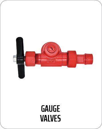
Proper mounting of solenoid valves and direct mount solenoid valves is crucial for system stability. Correct installation ensures reliable operation and prevents malfunctions, particularly in demanding environments. Choosing the right actuator depends on the specific application, with pneumatic favored for remote, rugged environments, and electric actuators offering precise control where needed.


Control Systems and Speed Controllers

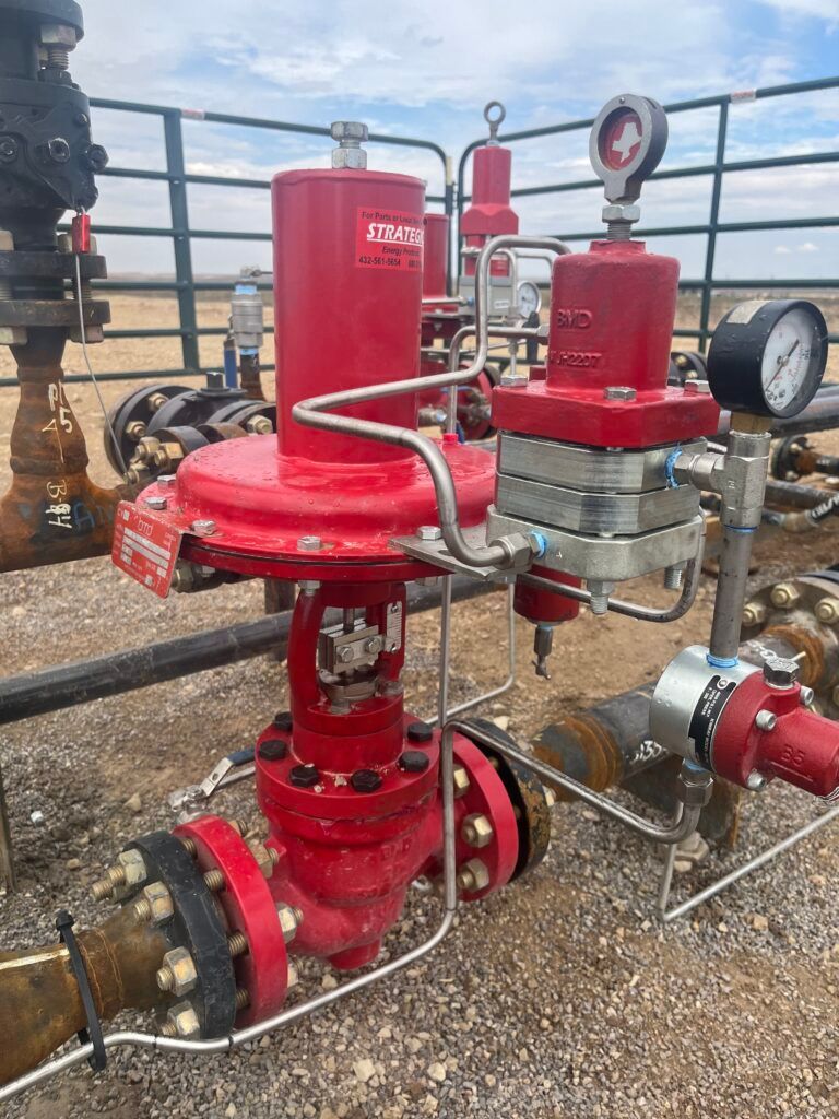
Pneumatic control systems and speed controllers play a vital role in optimizing actuator performance. Control systems use compressed air to power machinery and regulate the flow and pressure applied to actuators, ensuring precise movement of mechanical parts. Sensors within these systems monitor variables like pressure and temperature, automatically adjusting pumps or motors to maintain optimal conditions.


Speed controllers, also known as flow controls, enhance actuator efficiency by regulating the flow rate in one direction while allowing full flow in the other. This ensures controlled, precise movement in one direction and faster return in the opposite. Integrated pilot check valves and adjustable stems or knobs further allow for fine-tuning of airflow, while built-in indicators provide real-time diagnostics. By using meter-out or meter-in valves, speed controllers can precisely manage exhaust or input air, contributing to smoother, more efficient actuator operations.


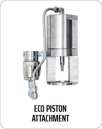
Eco piston – zero emissions actuator

The eco piston is a unique zero-emissions actuator that offers a sustainable alternative to traditional pneumatic systems. Unlike pneumatic systems that require an air compressor, the eco piston operates using gas, which circulates through the system without being exhausted. This closed-loop design eliminates the need for a compressor while maintaining the benefits of pneumatic-like control.


By looping gas back into the system, the eco piston provides reliable operation without the energy consumption or environmental impact of compressed air systems. This innovative technology brings a new level of efficiency and control to the market, combining the best of both pneumatic and electric actuators while helping industries reduce emissions and meet stringent environmental standards.


FAQs

  1. What distinguishes instrument air from process air?
    Instrument air is pressurized air, typically up to 20 psi, used mainly for control purposes such as operating thermostats and pneumatic controls, similar to how low voltage is used in electrical systems to operate relays and contactors. In contrast, process air is utilized directly in industrial processes.
  2. What is the function of an instrument air system?
    An instrument air system is designed to ensure a continuous supply of compressed air that meets the necessary quality and pressure standards for operating instruments, controls, and other station utilities.
  3. Why do control valves require instrument air?
    Instrument air is essential in plants for multiple functions, primarily for actuating control valves and operating pneumatic instruments. These control valves adjust the flow, pressure, and level of process fluids, while pneumatic instruments are used to monitor and manage these parameters.
  4. What role does a pneumatic actuator play?
    Pneumatic actuators are mechanisms that transform the energy of compressed air or gas into mechanical motion. This motion is then used to control one or more final control elements in various applications.


By Website Editor July 11, 2025
How to Maintain & Troubleshoot Relief Valves for Long-Term Performance Relief valves serve as essential safety equipment in oil and gas operations, regulating system pressures to safe levels while preventing destructive system failures. They operate as safety devices for pipelines, separators, and storage tanks throughout upstream and midstream oil and gas systems. BMD produces spring-loaded pressure relief valves that fulfill the highest requirements for durability, corrosion resistance, and reliability. However, even the most durable valves require scheduled maintenance and prompt troubleshooting to achieve optimal performance. Failing to maintain equipment properly leads to operational downtime, increased safety risks, and costly repair expenses. The following article provides instruction for relief valve maintenance and troubleshooting to ensure BMD valves operate safely and efficiently throughout their extended lifespan. Understanding BMD Relief Valves BMD relief valves are reliable and long-lasting. They can handle high-pressure systems, protecting against overpressure situations that could otherwise compromise the integrity of pipelines, storage tanks, and other critical equipment. BMD offers spring-loaded pressure relief valves that serve multiple applications across the oil and gas sector. The valves are in pipelines, separators, and storage tanks, where they protect equipment from overpressure. BMD valves surpass American design standards to deliver peak performance in demanding operational conditions. Common features include: Corrosion Resistance: BMD relief valves are designed to withstand corrosive environments commonly found in oil and gas operations, ensuring durability and a longer service life. Spring-Loaded Design: These valves provide reliable pressure relief by automatically opening when the system pressure exceeds the preset limit. American-Made Durability: Designed and manufactured in the U.S., BMD relief valves offer a high level of precision, performance, and safety. When properly installed and maintained, these valves can significantly improve the safety and efficiency of your oil and gas systems. Understanding their design and function is key to performing effective maintenance and troubleshooting. Why Relief Valve Maintenance is Critical Relief valves protect oil and gas operations by preventing overpressure, which can stop leaks, prevent equipment damage, and prevent catastrophic failures. The relief valves require regular maintenance to maintain their optimal operational state. Poorly maintained relief valves can cause various issues, such as: Worn seals or improper valve seating can result in leaks that compromise system pressure and cause safety hazards. If a valve opens too frequently or at the wrong pressure, it can cause unnecessary pressure drops that disrupt operations. Accumulation of debris or corrosion inside the valve can block the flow path, reducing the valve’s effectiveness. Regular inspection and maintenance can help detect and resolve these issues before they escalate. BMD recommends inspecting relief valves regularly based on operational conditions, including pressure cycles and environmental factors. Follow the manufacturer’s guidelines for maintenance intervals to ensure that valves perform reliably over time. Relief Valve Standards & Maintenance Recommendations BMD manufactures safety relief valves under Section XIII of the ASME code. To maintain compliance and performance, all relief valves need to be sent to a qualified VR shop for reset and recertification—this process cannot be performed by the end user. In addition, BMD strongly recommends that customers have a maintenance program in place that includes annual re-certification by a National Board certified shop holding a VR stamp to ensure safety, reliability, and regulatory compliance. Relief Valve Troubleshooting: Common Issues and Fixes Regular maintenance does not prevent relief valves from developing problems. The following section outlines typical problems together with specific troubleshooting procedures for BMD valves. The valve fails to open at its specified pressure setting. Possible Causes: Incorrect valve settings or blockage. Troubleshooting: The spring condition should be checked for wear while verifying that the valve operates at its designated pressure setting. The valve components need cleaning to remove any blockages that might exist. The valve operates at higher frequencies than expected or before reaching the set pressure. Possible Causes: Fluctuating process pressure, debris under the seat, or incorrect settings. Troubleshooting: The valve seat should be inspected for debris while verifying that the pressure settings match the specifications. The necessary adjustments or replacements should be made to the components. The valve develops leaks after its activation. Possible Causes: Seat wear, seal damage, or improper reassembly. Troubleshooting: The internal components need replacement or reseating according to the situation. All parts need correct alignment during reassembly to stop leaks from occurring. Audible chattering or vibrations. Possible Causes: Back pressure, poor mounting, or improper valve sizing. Troubleshooting: Check both the mounting and installation procedures and backpressure conditions. BMD provides installation guidelines which help users select appropriate valves and determine correct flow sizes. Long-Term Performance Tips for BMD Relief Valves The following best practices will help you achieve long-term performance: Create a maintenance schedule that considers operating conditions and manufacturer recommendations. Maintain detailed documentation of all maintenance work, inspection results, and replacement records. Technicians should receive BMD-specific maintenance training to perform proper care of the equipment. The use of OEM parts for all repair and rebuild operations will preserve both performance and reliability. Send the valve to BMD for factory service or certified testing when issues persist or when the valve exhibits significant signs of wear. Conclusion The oil and gas industry requires regular maintenance and accurate troubleshooting of relief valves to ensure safe and reliable operations. BMD relief valves are built to withstand demanding conditions, but their long-term performance depends on regular maintenance. The maintenance and troubleshooting guidelines in this guide will help you maintain relief valve reliability, which leads to better system safety and compliance, along with operational efficiency. For further assistance with OEM parts or technical support, contact BMD.
May 30, 2025
Introduction Control Valves play a crucial role in modern oil and gas operations, managing flow, maintaining pressure, and supporting overall process stability. In harsh upstream and midstream environments, the performance and reliability of these valves can significantly impact operational safety, efficiency, and profitability. At Beaumont Manufacturing and Distribution (BMD), we specialize in American-made control valves engineered for the extreme conditions found in oilfields and processing facilities. With decades of industry experience and a commitment to quality, our valves are trusted worldwide for their durability and field-tested performance. In this guide, we’ll explore the anatomy of a BMD control valve , breaking down the core components and highlighting what makes our products stand out in demanding applications. What Is a Control Valve? A control valve is a mechanical device that regulates the flow of fluid—such as oil, gas, steam, or water—by varying the size of the flow passage in response to signals from a control system. These valves allow for continuous modulation, unlike isolation valves, which are either fully open or fully closed. Why Control Valves Matter in Oil and Gas In the oil and gas sector, precision and reliability are everything. Control valves must: Maintain steady volume levels Regulate temperature via fluid control Ensure consistent flow rates Respond quickly to changes in process conditions Operate under high-pressure, high-temperature, and corrosive environments BMD’s valves are engineered specifically for these needs. Whether you’re operating in the Permian Basin or offshore platforms, our valves help you maintain safe, smooth, and optimized processes. Core Components of a BMD Control Valve A control valve is more than the sum of its parts—it’s a fully integrated system designed for optimal control and longevity. Here’s a closer look at each component in a BMD valve and the value it brings to the table. Valve Body The valve body is the primary pressure-retaining structure and the base of the control valve. It houses internal components and provides the flow path for the process fluid. BMD Valve Body Features: Materials: High-grade cast or forged carbon steel, stainless steel. Designs: Globe-style and angle-body configurations to suit different space and flow requirements. Compliance: All valve bodies Designed in accordance with ASME and other piping code standards. Actuator The actuator converts a control signal into mechanical motion, moving the valve plug, disc, or ball to modulate the flow. BMD Actuator Options: Pneumatic Actuators: Reliable even in remote locations with limited power sources. Actuators are available as either Reverse Acting (Fail-Closed) or Direct Acting (Fail-Open) to default to a safe position in power loss situations. Electric Actuator: An emissions-free device. Trim Assembly The trim refers to the internal elements directly responsible for flow control, including the plug, seat, and stem. These components determine the valve’s flow characteristic and shut off performance. BMD Trim Advantages: Material Selection: Hardened stainless steel, tungsten carbide, D2 tool steel and other specialty coatings to resist wear and galling. Flow Characteristics: Linear, equal percentage, or quick-open profiles. Noise and Cavitation Control: Anti-cavitation trim designs available for high ΔP (differential pressure) applications. We do not offer any anti-noise or anti-cav trim. Metal to metal seating: BMD offers metal to metal seating in our larger full port valves for extended life in erosive service. Unbalanced large valve trim: Our offering of unbalanced trim is great for sandy service so that sand doesn’t pack behind the valve plug like on a balanced valve. Our trim extends service life in abrasive media applications like sand-laden crude or produced water. Each trim set is precision-engineered and pressure-tested for tight shutoff and responsive modulation. Bonnet The bonnet serves as a pressure boundary and provides a guide for the stem while supporting the packing system. BMD Bonnet Design Features: Bolted or Pressure-Sealed not sure what ‘pressure sealed’ means. The design of the bonnet will vary by valve series but there are no options within a particular valve series.: Available depending on the pressure class and maintenance preference. Materials: Compatible with body materials to meet the same pressure, temperature and service as the body. BMD’s bonnet assemblies are designed with easy maintenance in mind, and can be removed to service the valve without taking the valve body out of line. Packing and Sealing System The packing system prevents leakage along the valve stem by creating a seal between internal and external environments. BMD Sealing Solutions: All BMD control valves come with BMD’s patent pending low-emissions packing system. Packing Materials: Engineering PTFE and rubber packing set. Environmental Compliance: Certified to ISO 15848 Live-Loaded Packing: No external packing adjustment is needed. Excellent performance in high cycle applications. Integrated Performance: Engineered as a Complete System At BMD, we don’t just build valves—we engineer systems. Each valve is a culmination of component synergy, where design tolerances and material compatibility are fine-tuned to deliver peak performance. Performance Testing Before a valve leaves our Beaumont facility, it undergoes a battery of performance tests, including: Hydrostatic Pressure Testing (per API 598) Leakage Testing (ANSI/FCI 70-2 Class IV–VI) Actuator Stroke and Response Verification This comprehensive quality control ensures that BMD control valves deliver predictable, reliable service in any condition, from high-pressure gas transmission to corrosive chemical injection. Common Applications of BMD Control Valves Our valves are field-proven in critical systems, including: Oil Production Units – separators, heater treaters, and flowlines Gas Processing – dehydration units, compressors, and scrubbers Midstream Pipelines – pressure regulation and pigging stations Water Injection and Disposal – high-pressure, high-volume service Each application demands specific capabilities—from pressure rating to media compatibility—which is why we offer a wide range of valve configurations and customizations. What Sets BMD Control Valves Apart? When choosing a control valve manufacturer, it’s not just about specs—it’s about partnership. Here’s why oil and gas operators trust BMD: Made in the U.S.A. - All our control valves are manufactured in the United States, with full traceability and quality assurance. This not only supports American jobs but ensures faster lead times and easier compliance with domestic sourcing requirements. Short Lead Times - Thanks to in-house manufacturing and a streamlined supply chain, BMD delivers where others delay. For mission-critical projects, our fast turnaround times reduce costly downtime. Unmatched Customer Support - We don’t just sell valves—we support systems. Our engineers work directly with your field teams to select, troubleshoot, and maintain your valve assets for long-term performance. Reduce Emissions with BMD’s Super Red packing - BMD’s patent pending Super Red packing system is standard in all BMD’s control valve lines. This proprietary material blend has been tested to ISO 15848 and will help ensure site OOOO compliance. Conclusion: Precision You Can Trust Understanding the components and functions of a control valve is essential for engineers and operators tasked with optimizing performance and reducing risk in oil and gas systems. With Beaumont Manufacturing and Distribution, you’re not just buying a valve—you’re investing in a product designed to perform where it matters most. Each BMD valve reflects our commitment to rugged design, material excellence, and technical support. Whether you’re retrofitting an existing system or building a new facility, we’re ready to help you select the ideal control solution. Need Expert Help? Let BMD support your operation with precision-engineered solutions and real-world experience. Contact our team today for expert technical guidance or to request a quote tailored to your application.
More Posts