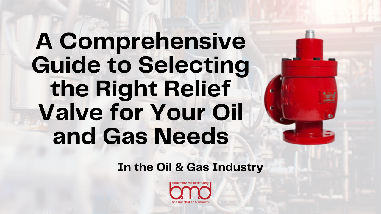
A Comprehensive Guide to Selecting the Right Relief Valve for Your Oil and Gas Needs

satha • April 11, 2025

Oil and gas production involves managing large volumes of hydrocarbon fluids, often under high temperatures and pressures. Due to this, production systems—composed of wells, wellheads, pipelines, vessels, pumps, and compressors—must be equipped with robust protection mechanisms to prevent failures caused by overpressure. 


Among these, relief valves are the most vital components for overpressure protection within a pressurized system. Their importance is such that they are commonly referred to in the industry as “Ultimate Safeguards.” 


Relief valves safeguard oil and gas production systems by preventing ruptures caused by excessive pressure. They help shield personnel, the environment, and infrastructure from catastrophic outcomes that can be caused by uncontrolled hydrocarbon release. They contribute to operational efficiency by ensuring that pressure excursions are safely handled while preserving the integrity of production systems.


Beaumont Manufacturing and Distribution Company (BMD) is a trusted relief valve supplier to the oil and gas industry, with a range of safety relief valves that are well-suited for overpressure protection of production equipment.

This guide will help you to select the correct relief valves for your oil and gas applications. It covers the working principles, key selection criteria, regulatory aspects, proper installation, and maintenance practices.


Understanding Relief Valves in Oil and Gas Applications

A relief valve is a pressure control device that opens to relieve excess pressure and recloses once conditions normalize. A conventional relief valve has an inlet nozzle, a movable disc, and a spring that sets the pressure threshold. By balancing forces, fluid pressure exceeding the spring’s set limit opens the valve, safely releasing excess fluid. When pressure falls, the spring reseats the disc, closing the valve. This mechanism prevents overpressure and ensures safe system operation.


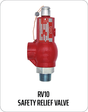
BMD’s 
RV10 relief valves are precision-built for overpressure protection of production equipment and designed for longevity, efficiency, and reliability in the field. RV10 relief valves are manufactured in accordance with the ASME BPVC, and capacity tested and certified by the National Board.


Relief valves in oil and gas operations prevent overpressure in equipment like separators, compressors, and pipelines. These situations could arise, for example, due to blockages, surges, thermal expansion, or control failures. By opening at preset pressure levels, relief valves safely release excess fluid into a relief header system, protecting equipment from rupture and ensuring operational safety.


Key Factors to Consider When Selecting a Relief Valve

Choosing the right relief valve involves evaluating several key factors to match the valve with system requirements effectively. Some key factors are:


Operating Pressure and Set Pressure:  To avoid leakage due to simmering action when the maximum operating pressure approaches the relief valve set pressure, sufficient margin must be provided between the two. For most applications the operating pressure should be no more than 90% of the set pressure. If vibration is present or pressure surges are expected then it should be even lower.


Flow Capacity (Sizing Considerations):  Relief valves must be sized for the worst-case relieving scenario (governing case). When sizing a relief valve the required capacity, set pressure, relieving temperature, and fluid properties should be specified in order to properly select the correct size valve. In some cases multiple valves may be used in parallel. Flow capacity calculations are performed per API and ASME codes.


Type of Fluid/Gas Being Processed:  The physical and chemical properties of the fluid being handled impact the size of relief valve needed, as well as choice of materials. All operating and relieving scenarios must be considered while evaluating the fluid properties. For example, crude oil may be light or viscous, there may be fouling asphaltenes or waxy substances. Natural gas may contain corrosive acid components. Gas with free water may form hydrates.


Temperature and Environmental Conditions:  Relief valves must retain their integrity at conditions to which they are constantly exposed as well as at relieving conditions. High temperatures need heat-resistant components, while cryogenic systems demand materials suited to extreme cold. Environmental factors such as ambient temperature, humidity, precipitation, desert conditions, and offshore service, will affect the choice of materials.


Material Compatibility:  It must be ensured that the materials used in the relief valve are compatible with the process fluid at all operating and relieving conditions. For example, relieving scenarios may be at high temperatures and pressures whereas operating conditions may be mild. Corrosion resistance is essential. BMD relief valves are manufactured using different materials as shown in Figure 1.


BMD Relief Valves and Their Applications

Overpressure risks in the oil and gas industry encompass a wide range of operating conditions. BMD’s RV10 series of spring-loaded relief valves span a set-pressure range of 15-3000 psi and temperature range of -50 oF-400 o F. Available in different models to suit varying requirements, RV10 safety relief valves are an ideal choice for overpressure protection of compressors, scrubbers, separators, pipelines and other systems where overpressure protection may be required. BMD’s RV10 Relief Valves incorporate a non-rising stem design that gives the disk full guidance, while opening and closing.


This is coupled with a soft seat design that ensures long lasting set pressure repeatability and bubble tight shut-off. The shorter stem makes the valve compact and ideal for tight spaces. The RV10 is ASME-certified for gas and liquid service and is available in NPT and flanged connections. The flanged relief valve sizes meet API 526 dimensions. The RV10 is manufactured in accordance with the ASME Boiler and Pressure Vessel Code, capacity tested and certified by the National Board, and meets the requirements of Sec on VIII, Division 1 of the ASME Code. 


Regulatory Compliance and Industry Standards for Relief Valves

Relief valve design and operation are subject to rigorous regulations established by various organizations. For oil and gas installations within the USA, the most important national standards are as follows:

API Standard 520, Part 1 Sizing, Selection, and Installation of Pressure-relieving Devices Part I—Sizing and Selection.

API Standard 520 Part II, Sizing, Selection, and Installation of Pressure-relieving Devices Part II—Installation.

API Standard 521, Pressure-relieving and Depressuring Systems.

API Standard 526, Flanged Steel Pressure-relief Valves.

API Standard 527: Pressure Relief Valve Seat Tightness.

ASME Boiler and Pressure Vessel Code (BPVC).

Regular inspections, testing, and documentation are critical for demonstrating compliance during audits.


Best Practices for Installation and Maintenance

Relief valves should always be installed and maintained according to manufacturer guidelines and industry standards. Position the valve vertically. The inlet piping should be short and direct, without pockets. Ensure nameplate details are visible. Outlet piping should be free, draining away from the valve to prevent liquid accumulation. Provide proper supports for valve and piping considering reaction forces.

Relief valves are not an end user serviceable device. They must be worked on by a certified VR shop. They should be tested annually at minimum to verify set pressure and that the valve is free to operate.


Choosing the Right Safety Relief Valve Manufacturer

Selecting the right safety relief valve manufacturer is crucial for system performance and safety.


What to Look for in a Reliable Relief Valve Supplier

Quality Certifications and Industry Reputation

Choose a supplier who values meeting the highest industry standard, and with proven expertise in industry-specific valves. Ensure they meet quality standards and certification like ISO-9001 and ASME certification, showcasing compliance and a commitment to quality management and excellence. A strong reputation backed by customer reviews and industry recognition is essential.


Technical Support Availability

Since relief valves are critical to the safety of oil and gas production facilities, assurance of prompt and reliable technical support from suppliers is very important.


Conclusion

Selecting the right relief valve involves assessing key factors like operating pressure, material compatibility and selecting a manufacturer who is reputable and values the highest quality standards. Choosing a high quality relief valve for your oil and gas system is vital to the integrity of your system, and the safety and protection of your environment and personnel. Properly specified, installed, and maintained relief valves ensure safety, operational integrity, and compliance with stringent industry standards. Protect your people, your environment, and your infrastructure with BMD’s trusted safety relief valves. Contact BMD today for expert guidance and top-tier relief valve solutions for your oil and gas system.


By Website Editor July 11, 2025
How to Maintain & Troubleshoot Relief Valves for Long-Term Performance Relief valves serve as essential safety equipment in oil and gas operations, regulating system pressures to safe levels while preventing destructive system failures. They operate as safety devices for pipelines, separators, and storage tanks throughout upstream and midstream oil and gas systems. BMD produces spring-loaded pressure relief valves that fulfill the highest requirements for durability, corrosion resistance, and reliability. However, even the most durable valves require scheduled maintenance and prompt troubleshooting to achieve optimal performance. Failing to maintain equipment properly leads to operational downtime, increased safety risks, and costly repair expenses. The following article provides instruction for relief valve maintenance and troubleshooting to ensure BMD valves operate safely and efficiently throughout their extended lifespan. Understanding BMD Relief Valves BMD relief valves are reliable and long-lasting. They can handle high-pressure systems, protecting against overpressure situations that could otherwise compromise the integrity of pipelines, storage tanks, and other critical equipment. BMD offers spring-loaded pressure relief valves that serve multiple applications across the oil and gas sector. The valves are in pipelines, separators, and storage tanks, where they protect equipment from overpressure. BMD valves surpass American design standards to deliver peak performance in demanding operational conditions. Common features include: Corrosion Resistance: BMD relief valves are designed to withstand corrosive environments commonly found in oil and gas operations, ensuring durability and a longer service life. Spring-Loaded Design: These valves provide reliable pressure relief by automatically opening when the system pressure exceeds the preset limit. American-Made Durability: Designed and manufactured in the U.S., BMD relief valves offer a high level of precision, performance, and safety. When properly installed and maintained, these valves can significantly improve the safety and efficiency of your oil and gas systems. Understanding their design and function is key to performing effective maintenance and troubleshooting. Why Relief Valve Maintenance is Critical Relief valves protect oil and gas operations by preventing overpressure, which can stop leaks, prevent equipment damage, and prevent catastrophic failures. The relief valves require regular maintenance to maintain their optimal operational state. Poorly maintained relief valves can cause various issues, such as: Worn seals or improper valve seating can result in leaks that compromise system pressure and cause safety hazards. If a valve opens too frequently or at the wrong pressure, it can cause unnecessary pressure drops that disrupt operations. Accumulation of debris or corrosion inside the valve can block the flow path, reducing the valve’s effectiveness. Regular inspection and maintenance can help detect and resolve these issues before they escalate. BMD recommends inspecting relief valves regularly based on operational conditions, including pressure cycles and environmental factors. Follow the manufacturer’s guidelines for maintenance intervals to ensure that valves perform reliably over time. Relief Valve Standards & Maintenance Recommendations BMD manufactures safety relief valves under Section XIII of the ASME code. To maintain compliance and performance, all relief valves need to be sent to a qualified VR shop for reset and recertification—this process cannot be performed by the end user. In addition, BMD strongly recommends that customers have a maintenance program in place that includes annual re-certification by a National Board certified shop holding a VR stamp to ensure safety, reliability, and regulatory compliance. Relief Valve Troubleshooting: Common Issues and Fixes Regular maintenance does not prevent relief valves from developing problems. The following section outlines typical problems together with specific troubleshooting procedures for BMD valves. The valve fails to open at its specified pressure setting. Possible Causes: Incorrect valve settings or blockage. Troubleshooting: The spring condition should be checked for wear while verifying that the valve operates at its designated pressure setting. The valve components need cleaning to remove any blockages that might exist. The valve operates at higher frequencies than expected or before reaching the set pressure. Possible Causes: Fluctuating process pressure, debris under the seat, or incorrect settings. Troubleshooting: The valve seat should be inspected for debris while verifying that the pressure settings match the specifications. The necessary adjustments or replacements should be made to the components. The valve develops leaks after its activation. Possible Causes: Seat wear, seal damage, or improper reassembly. Troubleshooting: The internal components need replacement or reseating according to the situation. All parts need correct alignment during reassembly to stop leaks from occurring. Audible chattering or vibrations. Possible Causes: Back pressure, poor mounting, or improper valve sizing. Troubleshooting: Check both the mounting and installation procedures and backpressure conditions. BMD provides installation guidelines which help users select appropriate valves and determine correct flow sizes. Long-Term Performance Tips for BMD Relief Valves The following best practices will help you achieve long-term performance: Create a maintenance schedule that considers operating conditions and manufacturer recommendations. Maintain detailed documentation of all maintenance work, inspection results, and replacement records. Technicians should receive BMD-specific maintenance training to perform proper care of the equipment. The use of OEM parts for all repair and rebuild operations will preserve both performance and reliability. Send the valve to BMD for factory service or certified testing when issues persist or when the valve exhibits significant signs of wear. Conclusion The oil and gas industry requires regular maintenance and accurate troubleshooting of relief valves to ensure safe and reliable operations. BMD relief valves are built to withstand demanding conditions, but their long-term performance depends on regular maintenance. The maintenance and troubleshooting guidelines in this guide will help you maintain relief valve reliability, which leads to better system safety and compliance, along with operational efficiency. For further assistance with OEM parts or technical support, contact BMD.
May 30, 2025
Introduction Control Valves play a crucial role in modern oil and gas operations, managing flow, maintaining pressure, and supporting overall process stability. In harsh upstream and midstream environments, the performance and reliability of these valves can significantly impact operational safety, efficiency, and profitability. At Beaumont Manufacturing and Distribution (BMD), we specialize in American-made control valves engineered for the extreme conditions found in oilfields and processing facilities. With decades of industry experience and a commitment to quality, our valves are trusted worldwide for their durability and field-tested performance. In this guide, we’ll explore the anatomy of a BMD control valve , breaking down the core components and highlighting what makes our products stand out in demanding applications. What Is a Control Valve? A control valve is a mechanical device that regulates the flow of fluid—such as oil, gas, steam, or water—by varying the size of the flow passage in response to signals from a control system. These valves allow for continuous modulation, unlike isolation valves, which are either fully open or fully closed. Why Control Valves Matter in Oil and Gas In the oil and gas sector, precision and reliability are everything. Control valves must: Maintain steady volume levels Regulate temperature via fluid control Ensure consistent flow rates Respond quickly to changes in process conditions Operate under high-pressure, high-temperature, and corrosive environments BMD’s valves are engineered specifically for these needs. Whether you’re operating in the Permian Basin or offshore platforms, our valves help you maintain safe, smooth, and optimized processes. Core Components of a BMD Control Valve A control valve is more than the sum of its parts—it’s a fully integrated system designed for optimal control and longevity. Here’s a closer look at each component in a BMD valve and the value it brings to the table. Valve Body The valve body is the primary pressure-retaining structure and the base of the control valve. It houses internal components and provides the flow path for the process fluid. BMD Valve Body Features: Materials: High-grade cast or forged carbon steel, stainless steel. Designs: Globe-style and angle-body configurations to suit different space and flow requirements. Compliance: All valve bodies Designed in accordance with ASME and other piping code standards. Actuator The actuator converts a control signal into mechanical motion, moving the valve plug, disc, or ball to modulate the flow. BMD Actuator Options: Pneumatic Actuators: Reliable even in remote locations with limited power sources. Actuators are available as either Reverse Acting (Fail-Closed) or Direct Acting (Fail-Open) to default to a safe position in power loss situations. Electric Actuator: An emissions-free device. Trim Assembly The trim refers to the internal elements directly responsible for flow control, including the plug, seat, and stem. These components determine the valve’s flow characteristic and shut off performance. BMD Trim Advantages: Material Selection: Hardened stainless steel, tungsten carbide, D2 tool steel and other specialty coatings to resist wear and galling. Flow Characteristics: Linear, equal percentage, or quick-open profiles. Noise and Cavitation Control: Anti-cavitation trim designs available for high ΔP (differential pressure) applications. We do not offer any anti-noise or anti-cav trim. Metal to metal seating: BMD offers metal to metal seating in our larger full port valves for extended life in erosive service. Unbalanced large valve trim: Our offering of unbalanced trim is great for sandy service so that sand doesn’t pack behind the valve plug like on a balanced valve. Our trim extends service life in abrasive media applications like sand-laden crude or produced water. Each trim set is precision-engineered and pressure-tested for tight shutoff and responsive modulation. Bonnet The bonnet serves as a pressure boundary and provides a guide for the stem while supporting the packing system. BMD Bonnet Design Features: Bolted or Pressure-Sealed not sure what ‘pressure sealed’ means. The design of the bonnet will vary by valve series but there are no options within a particular valve series.: Available depending on the pressure class and maintenance preference. Materials: Compatible with body materials to meet the same pressure, temperature and service as the body. BMD’s bonnet assemblies are designed with easy maintenance in mind, and can be removed to service the valve without taking the valve body out of line. Packing and Sealing System The packing system prevents leakage along the valve stem by creating a seal between internal and external environments. BMD Sealing Solutions: All BMD control valves come with BMD’s patent pending low-emissions packing system. Packing Materials: Engineering PTFE and rubber packing set. Environmental Compliance: Certified to ISO 15848 Live-Loaded Packing: No external packing adjustment is needed. Excellent performance in high cycle applications. Integrated Performance: Engineered as a Complete System At BMD, we don’t just build valves—we engineer systems. Each valve is a culmination of component synergy, where design tolerances and material compatibility are fine-tuned to deliver peak performance. Performance Testing Before a valve leaves our Beaumont facility, it undergoes a battery of performance tests, including: Hydrostatic Pressure Testing (per API 598) Leakage Testing (ANSI/FCI 70-2 Class IV–VI) Actuator Stroke and Response Verification This comprehensive quality control ensures that BMD control valves deliver predictable, reliable service in any condition, from high-pressure gas transmission to corrosive chemical injection. Common Applications of BMD Control Valves Our valves are field-proven in critical systems, including: Oil Production Units – separators, heater treaters, and flowlines Gas Processing – dehydration units, compressors, and scrubbers Midstream Pipelines – pressure regulation and pigging stations Water Injection and Disposal – high-pressure, high-volume service Each application demands specific capabilities—from pressure rating to media compatibility—which is why we offer a wide range of valve configurations and customizations. What Sets BMD Control Valves Apart? When choosing a control valve manufacturer, it’s not just about specs—it’s about partnership. Here’s why oil and gas operators trust BMD: Made in the U.S.A. - All our control valves are manufactured in the United States, with full traceability and quality assurance. This not only supports American jobs but ensures faster lead times and easier compliance with domestic sourcing requirements. Short Lead Times - Thanks to in-house manufacturing and a streamlined supply chain, BMD delivers where others delay. For mission-critical projects, our fast turnaround times reduce costly downtime. Unmatched Customer Support - We don’t just sell valves—we support systems. Our engineers work directly with your field teams to select, troubleshoot, and maintain your valve assets for long-term performance. Reduce Emissions with BMD’s Super Red packing - BMD’s patent pending Super Red packing system is standard in all BMD’s control valve lines. This proprietary material blend has been tested to ISO 15848 and will help ensure site OOOO compliance. Conclusion: Precision You Can Trust Understanding the components and functions of a control valve is essential for engineers and operators tasked with optimizing performance and reducing risk in oil and gas systems. With Beaumont Manufacturing and Distribution, you’re not just buying a valve—you’re investing in a product designed to perform where it matters most. Each BMD valve reflects our commitment to rugged design, material excellence, and technical support. Whether you’re retrofitting an existing system or building a new facility, we’re ready to help you select the ideal control solution. Need Expert Help? Let BMD support your operation with precision-engineered solutions and real-world experience. Contact our team today for expert technical guidance or to request a quote tailored to your application.
More Posts